There are some variations which can happen like a combination of both frequencies: I measured this at the oscillator input of our ASIC. What I can measure with the oscilloscope is a spurious frequency of around 66 kHz which is close to double the frequency of the ultrasonic bath (35 kHz). If our device is put into an ultrasonic cleaning bath (electronic is sealed) the resonator starts to act up. It is optimized for the Murata CSTCC_G_A 2 MHz ceramic resonator. Our device uses a semi-custom IC which integrates the oscillator circuit, it's a simple Pierce oscillator with the matching resistors built into the ASIC.

However, as the performance has significantly improved, they are used in many other RF applications as well.I'm encountering a problem with a ceramic resonator as soon as our device is subjected to ultrasonic vibrations (ultrasonic cleaning bath). Originally ceramic filters were used as very low cost filters for broadcast radio receivers, both medium wave sets with typical IFs of 455 kHz and FM broadcast sets with IF stages at around 10.7 MHz. Ceramic filters are frequently used in the IF stages of superheterodyne receivers. Ceramic filters Ĭeramic resonators look similar to ceramic filters. This allows wider range of adjustments, which may be critical in devices operating in extreme (especially low) temperatures where the crystal's own temperature-frequency dependence could take it outside of the pullable range for the desired frequency. The frequency of the oscillator can be "pulled" in wider range than with high-Q crystal. The lower Q and higher frequency range achievable can be beneficial in use of TCXOs, temperature-compensated crystal oscillators.
#Osculator for ceramic resonator generator#
A ceramic resonator is often used in place of quartz crystals as a reference clock or signal generator in electronic circuitry due to its low cost and smaller size. They are used in timing circuitry for a wide array of applications such as TVs, VCRs, automotive electronic devices, telephones, copiers, cameras, voice synthesizers, communication equipment, remote controls and toys. Quartz has a 0.001% frequency tolerance, while PZT has a 0.5% tolerance. Applications Ĭeramic resonators can be used as the source of the clock signal for digital circuits such as microprocessors where the frequency accuracy is not critical. The third pin (if present typically the center pin) is connected to ground.

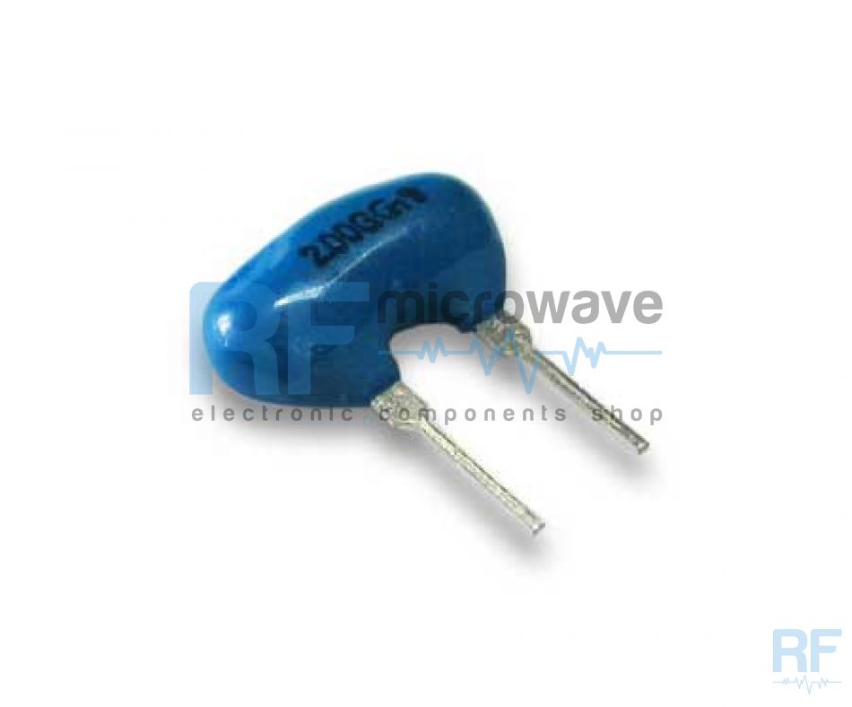
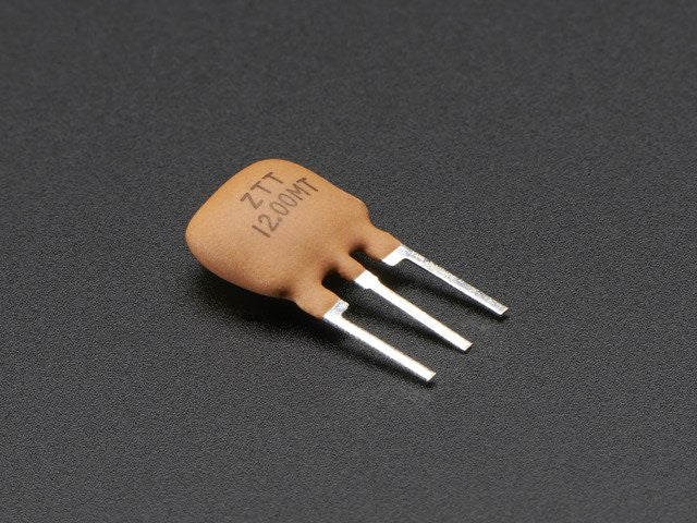
The oscillation takes place across two of the pins (connections). They come in both surface-mount and through-hole varieties with a number of different footprints.

The two pin devices are typically just the resonators themselves, while three and sometimes four pin devices are filters, often used in AM and FM broadcast radios as well as many other RF applications. The thickness of the ceramic substrate determines the resonant frequency of the device.Ī typical ceramic resonator package has either two or three connections. In operation, mechanical vibrations induce an oscillating voltage in the attached electrodes due to the piezoelectricity of the material. Like the similar quartz crystal, they are used in oscillators for purposes such as generating the clock signal used to control timing in computers and other digital logic devices, or generating the carrier signal in analog radio transmitters and receivers.Ĭeramic resonators are made of high-stability piezoelectric ceramics, generally lead zirconate titanate (PZT) which functions as a mechanical resonator.

When connected in an electronic oscillator circuit, resonant mechanical vibrations in the device generate an oscillating signal of a specific frequency. A ceramic resonator is an electronic component consisting of a piece of a piezoelectric ceramic material with two or more metal electrodes attached.


 0 kommentar(er)
